Last updated on: February 28, 2025
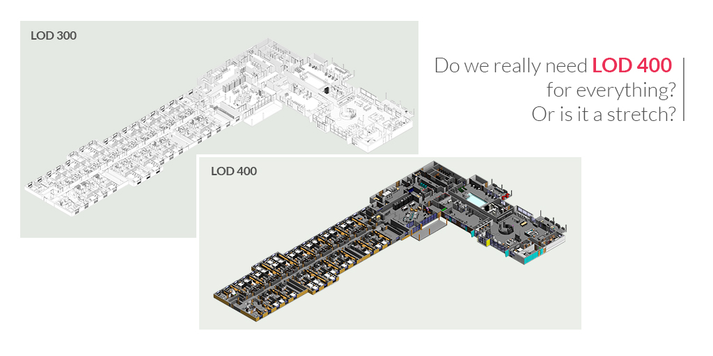
In this blog, we want to discuss a very common debate that prevails during the initiation of the project- Do we really need LOD 400?
The Project Owners (along with the Owner’s Representative) usually demand everything in the highest Level of Detail possible. They expect General Contractors to model and visualize every nut and bolt associated with the project.
Well, the real benefit of a higher Level of Detail is to gain a level of communication, coordination, and collaboration that increases the odds of completing the project within time, budget, and scope.
However, the success of the project depends upon the cost and resources associated with it. Modeling at a higher level increases the cost- time and money, and this could affect the productivity of the project.
It is important to strike a balance between different Levels of Detail (LOD). When we talk about the design model, it is obvious that there is a distinct difference in why trades are putting elements into the model. Some elements are for the purpose of coordination, while some trades place elements so that they could actively pre-fabricate the elements.
There is a difference between these two approaches. Hence, the key is to identify what is actually required to be modeled at LOD 400 or 500 because that will be essentially used by facility managers.
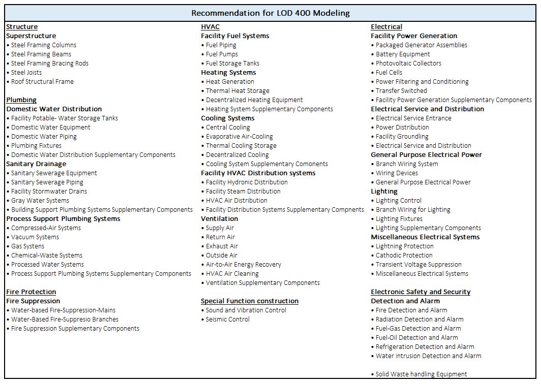
One can cherry-pick the essential trades and within the trades the required components/elements to be modeled at LOD 400. For example, MEPFP Hanger does make sense to be modeled at LOD 400 & LOD 500. But screws that are used for electrical switchboards can suffice with LOD 300 details.
LOD 350 was created by the BIMForum (an AIA AGC partnership) which is required to meet the design requirement, coordinate with the trades, and for installation like space allocation and shows the parts and pieces for assembly. Whereas, LOD 400 is a Fabrication level where the content meets the design criteria, space allocation and shows the parts and pieces for the assembly.
For example, if a structural engineer would design and create models for say, roof or foundation, in LOD 100 to 300 up to when the construction document is issued. But for the superstructure, they would design and engineer the elements like- trusses and members while the steel fabricator would create the actual model with 350 to 400 level of details.
Items that would require to be installed would be per fabrication model- LOD 400 so that you can finalize the steel sizing and the design for the structure materials with an easy click of the mouse or view a report and know the status.
Get the Insider Scoop: BIM Level of Development | LOD 100, 200, 300, 350, 400, 500

Don’t have the time to read the whole blog, no worries you can download it and read it at your convenient time.
Cons for stretching LOD 400
The process of using and modeling components at LOD 400 can come with some critical challenges that cannot be overlooked. The following are some limitations with LOD 400
1. Extra time and effort when compared to LOD 300
It takes additional time to research for the families than what is actually required. LOD 400 families may have to be created or modified if the suitable ones are not found from third-party. It becomes very time-consuming as it takes time to load families. It usually operates slower and requires higher RAM and CPU power. It is also important to organize the families, if not then trades could waste time looking for what is required.
LOD 400 families require more coordination time with fabricators/installers as compared to LOD 300 families as they rarely need any coordination with fabricators/installers.
2. Workflow challenges
When there are any design changes of any portion of the building after the initial design, the whole research process may need to occur again. For example, With LOD 300 the AHUs are unknown usually when construction documents are issued, so the contractor will coordinate size and location once the unit is purchased. Whereas with LOD 400, the unit is known, so the exact size and location is informed and might already be purchased and installed. If AHU changes, it might not work, and have to spend extra money to correct the situation. There can be chances of unforeseen clashes or if items are not installed as the design model that was used for fabrication.
Pros for LOD 400 in Revit
Although there are cons for a higher level of detail in the model as they bring upfront time dedication and cost, it saves the overall time on the construction schedule.
- It provides room for accurate Modeling of the equipment, actual locations, and clashes, and clearances requirement will be checked during the design phase instead of the construction phase as often occurs with LOD 300 projects.
- When exact equipment or system is shown in the exact place desired and agreed by the team, then extra pieces can be avoided to be fabricated and most in-field modifications can be avoided.
- The design model can be used for fabrication, which then becomes the record model with no changes, as long as items are installed as shown in the design model.
LOD 400 Revit Modeling
One of the important decisions for the A/E design team is to produce a Revit design model up to LOD 400. They work to meet the aggressive project schedules and how they can decrease the time to start the fabrication and installation process. Trades work with LOD 400 for fabrication and installation purposes. Certain structural, MEP elements modeled at LOD 400 prevent clashes and saves time and money on installation work.
For example, elements like duct, mechanical equipment, hot and chilled water can be modeled at LOD 400 and hangers location can be used for coordination and clash detection.
The fastest way to model at LOD 400 is to put in use what is easily available. Following pointers can be the alternatives:
- Contact product manufacturers to find out if they have any existing Revit families in place.
- Refer third-part BIM content provider’s website to match the requirement.
- If still not found, then model the elements for the rest which would be the case for only 5% of the elements.

Looking for LOD 100, 200, 300, 350, 400, 500 Modeling Services for your Design and Construction project. Contact us with your requirements.
LOD Modeling during different project workflows
Design-Bid-Build Projects
- Architect & Engineer design team will produce LOD 100 to 300 up to when Construction Documents (CD) are issued.
- LOD 350 to 400 Modeling would be done either by General Contractor or Sub-Contractor for Shop Drawings and Fabrication Models during the Construction Phase and then incorporated into the final Record Model which is handed over to the client.
Design-Assist Projects
- Architect & Engineer design team will produce LOD 100 to 300 up to when Construction Documents (CD) are issued.
- Initiation of Shop drawings and Fabrication model will be from a Schematic phase of the project and will pertain LOD 350 to 400 but will not be complete until the construction phase.
- The Fabrication Model is then incorporated into the Design Model if the elements are installed as per the Fabrication Model. Items not installed per the model will be updated in the Design Model to create a Record Model handed over to the Client.
Design-Build Projects
- Architect & Engineer design team will produce LOD 100 to 300 up to when Construction Documents (CD) are issued.
- The MEP trade contractors will create and share their Shop Drawings and Fabrication Models with LOD 350 to 400 details from Schematic Phase unitll the Construction Documents (CD) are issued.
- The Fabrication Model is then incorporated into the Design Model if the elements are installed as per the Fabrication Model. Items not installed per the model will be updated in the Design Model to create a Record Model handed over to the Client.
References
- Adapting LOD definition to meet BIM uses requirements and data modeling for linear infrastructures projects: using system and requirement engineering
- Design BIM LOD 400—Case Study of Volvo: Successes, Limitations, and Lessons Learned
- https://www.autodesk.com/autodesk-university/class/Design-BIM-LOD-400-Case-Study-Volvo-Successes-Limitations-and-Lessons-Learned-2017
About the Author

Coordination Manager / VDC Manager at United BIM
With over 10 years of experience in the AEC industry, Akash Patel is a seasoned Coordination Manager and VDC Manager at United BIM. His expertise lies in managing complex MEP-FP coordination projects and leveraging cutting-edge BIM technology to ensure seamless collaboration and precision. Akash is dedicated to delivering high-quality, detailed models that meet the demands of modern construction. He is passionate about optimizing workflows and driving innovation within the BIM field.


