BIM Guidelines by CT-DAS
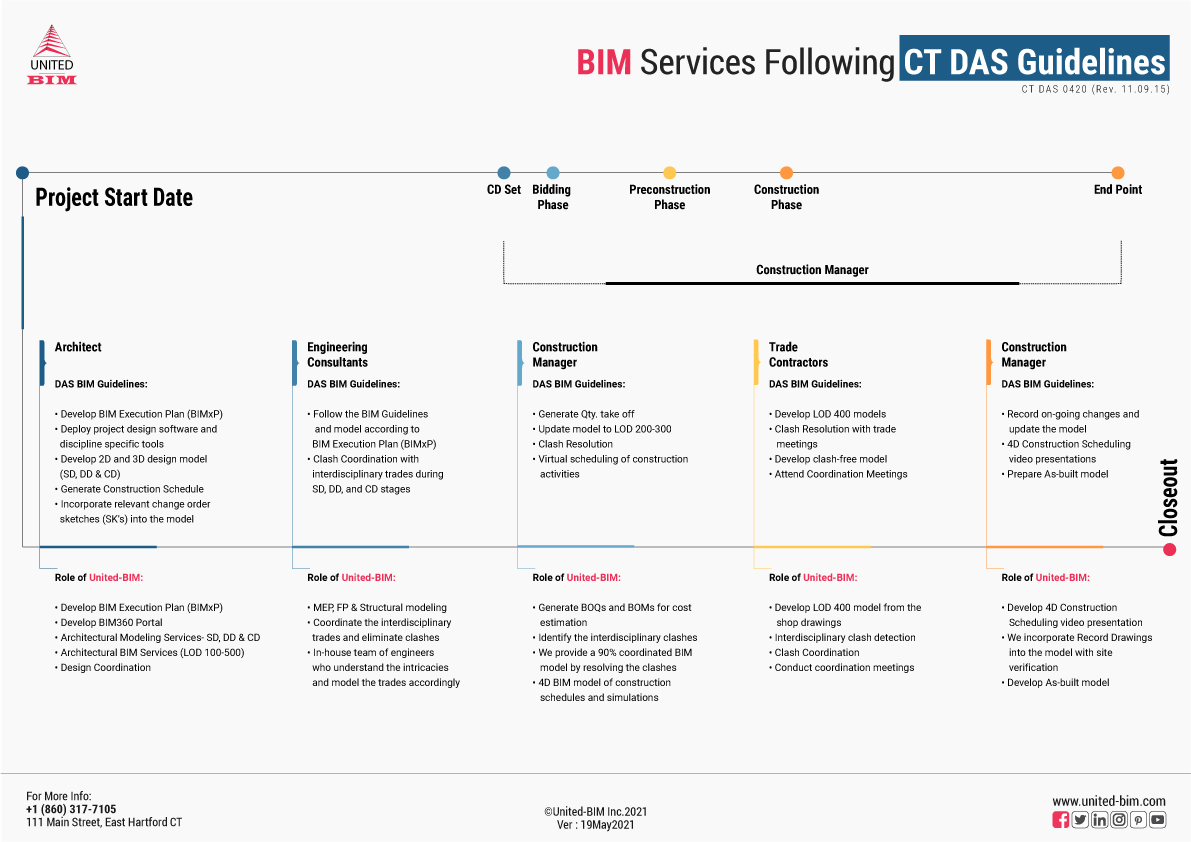
We are an East Hartford, CT-based BIM firm. We offer our services during the Design, Pre-construction, and Construction Phases of a project as per the Connecticut- Department of Administrative Services (CT-DAS) BIM Guidelines called out in revision 0420-11.09.15.
Our goal is to work with AEC companies of Connecticut and be a part of their team or an extended team and develop BIM models (design-intent & trade models) as per the BIM Execution Plan. Our experience includes working on projects of all types- new construction, renovation, fit-out, and all sizes of projects from 2500 SQFT to 600,000 SQFT.
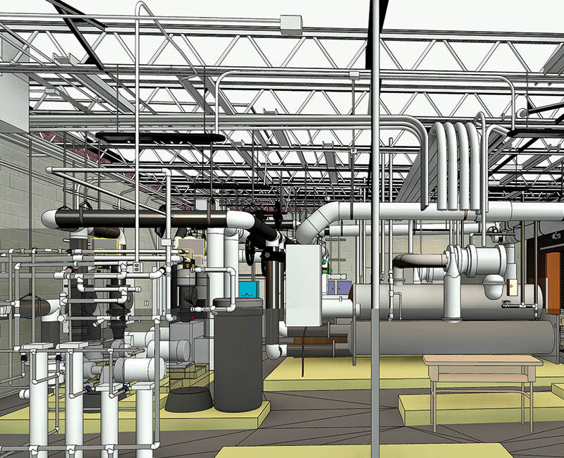
We have delivered BIM models to different kinds of projects, be it a school’s mechanical room, multi-residential, hotel, elementary school, or healthcare projects, etc. and that’s true for all types of project delivery methods – Design-bid-build (DBB), Design-build (DB), Construction Management at Risk, Design-negotiate-build (DNB), and Integrate Project Delivery (IPD) methods.
Our deliverables include- 2D drawings, 3D drawings/models, 4D Construction Phasing Model, 5D Cost Estimation and Quantity Takeoffs, 6D for Facility Management, 7D for building sustainability, and 8D for Safety and Security according to the required Level of Detail (100-500).
We understand the concern areas of our client and we know that it is very critical to have a single point of contact for the client when it comes to BIM modeling. Since we are local -based in Hartford, it gives us the advantage to be a part of client’s meetings in person (face-to-face) – project Kick-off, Design Phases, Construction Manager onboarding, construction startup, Subcontractor engagement, and closeout. There are 168 towns in Connecticut and we have worked on projects in Danbury, Glastonbury, Fairfield, West Hartford, Bristol, New Haven, Hamden, New London, Stamford, Manchester, Enfield, North Haven, Hampton, Bridgeport, etc.
BIM Following CT DAS Guidelines/Requirements
- BIM Execution Plan- Architects have to provide a BIM Execution Plan on the basis of the template provided by the Department. This Execution Plan will define and identify the A/E disciplines. The BIM Execution Plan will identify the proposed in-house or BIM outsourcing plan.
- BIM Portal- The Architect’s main responsibility is to deploy project design software and discipline-specific tools.
- They need to develop an FTP or project website and provide collaboration and communications tools throughout the design and construction phase.
- The BIM Portal established by the Architects will be shared with the MEP consultants and other engineering teams to develop and update the model on it.
- Design Coordination- The architect will be required to perform the required analysis and clash avoidance in the pre-construction phase.
- Develop and model the project design in 2D and 3D from the Schematic, Design Development & Construction Document Phase.
- Record Drawings- Incorporating relevant change order sketches (SKs) into the model
- We can develop a BIM Execution plan by following the guidelines of the Department.
- We can establish a BIM 360 portal for Architects for project communication and collaboration throughout the design and construction phase. We use various FTP platforms to communicate with our clients like- Dropbox, Google Drive, etc.
- We adhere to Uniformat and Omniclass standards for model element identification, classification as suggested by Department CAD standards, functional space naming, and room numbering in the BIM Execution Plan.
- We can provide drafting of the design of the project from the Schematic Design Phase, Design Development Phase, and Construction Document Phase.
- We can develop and model the design of the project, tag material components, systems, and/or assemblies generate schedules, and derive data.
- We can help MEP consultants to model their design and we can also perform clash detection and coordination services and ensure that complete design coordination takes place.
- Follow the BIM Guidelines laid out by the Department and model the elements, equipment, and components according to the BIM Execution Plan (BIMxP)
- Engineering consultants are responsible for performing clash coordination with interdisciplinary trades during all the phases SD, DD, and CD) and only then the Construction Document (CD) set is issued.
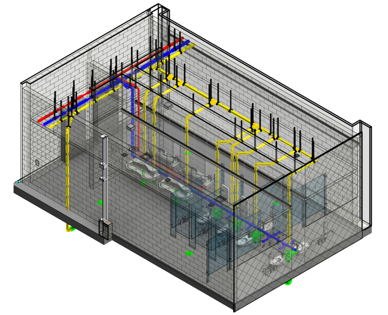
- We provide accurate MEP, FP, and Structural Modeling from LOD 100-500
- We provide coordination of interdisciplinary trades and eliminate clashes.
- Our in-house team of BIM modelers and engineers understands the intricacies and models the elements, equipment, and components according to the requirements laid in DAS guidelines.
Pre-construction Phase:
- Generate Quantity Take-offs and provide cost estimation
- Update the model to LOD 200-300
- Periodic clash detection reports and facilitates clash resolution reviews.
- CM will provide virtual scheduling with updates and utilize the upgraded modes during coordination meetings to inform tradesmen of affected phases of construction. The CM is responsible for using the model in the field to support reviews, site logistics, and ongoing construction.
Construction Phase-
- Record the ongoing design changes that take place during the construction and update the model with the same.
- The construction Manager is responsible for presenting the 4D Construction Video that includes sequences, schedules, and simulations.
- As-built Model- CM will develop an As-built model with site-verified changes in the design and incorporate all the change orders into the model.
Pre-construction Phase:
- We can develop a 5D BIM model for the accurate generation of Bills of Quantity (BOQs) and Bills of Materials (BOMs) that can help in providing accurate cost estimation.
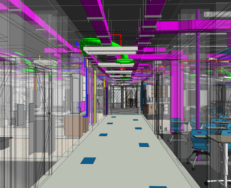
- Clash Detection Services- We provide clash detection services and report generation services for each model – highlighting the number & types of clashes, and the details of each clash location among different trades/disciplines.
- MEP Coordination Services- We provide an approx. 90% clash-free BIM model to our clients by working closely with the entire team to make collective decisions for the design changes or modifications.
Construction Phase:
- 4D BIM- We can develop an entire construction schedule that includes time-related data of the project development, showing how the project will be constructed and how the structure and site surroundings will appear at each stage.
- We can conduct the 4D Construction Scheduling video presentations with the project teams.
- We incorporate the record drawings or the change orders into the model by physically holding various site verifications.
- As-built Model- We create high-quality as-built BIM models that capture all kinds of changes that take place during construction with the help of As-Built drawings and using contractors and sub-contractors to mark up the notes.
- Develop LOD 400 models for the purpose of fabrication, assembly, and/or installation.
- Attending trade meetings and resolving interdisciplinary clashes.
- Develop a model that has no major clashes with other trades and is ready for construction
- We can develop the LOD 400 BIM model from the shop drawings provided by the trade contractors. The details and information contained by LOD 400 elements can be handed over directly to suppliers to manufacture the building components being represented.
- We can conduct coordination meetings to resolve the trade clashes
- We provide clash detection and report generation services for trade contractors
We Model Following Elements as per DAS, CT
Site Grading Surface | Manhole Locations | Pipe Inverts | Pipe Sizes | Surface Model Contours | Surrounding Buildings | Driveways | Parking areas | Walkways | Landscaping beds | Trees | Utility Poles | Street Furniture | Underground Utilities
Walls | Ceilings | Chases | Door | Window openings | Exterior Envelope | Roof | Stairs | Railings | Ratings, Masonry, Drywall, Shaft Wall, Glass Block | MEP Chases | Elevator Shafts | Stairwells | Finish Floor | Exterior Envelope | Furniture Layout | Equipment | Interior Storage Units
Spread footings | Piles | Foundations | Grade Breams | Beams | Columns | Girders | Framing | Bracing Sans Connection details | Shear Elements | Bearing Walls | Floor | Roof Decks | Elevator Shafts | Stairwell
Ducts | Air Handling Equipment | Boilers | Pumps | Associated Piping | Supply and Return Louvers | Grillers | Diffusers | Equipment clearances | Space Requirements | Gauge Readings | Access Plates | Valve Clearances
Conduit | Major Equipment | Switchgear | Transformers | Panel Boards | Generators | Conduit | Lighting Fixtures
Piping | Risers | Pitched Drawings | Pumps and Equipment | Fixtures | Sleeved Objects in exterior penetrations
Equipment | Risers | All Piping | AV/IT Security
4D BIM - Construction Scheduling
We develop a 4D Construction Phasing Model for constructability, costing, and scheduling purposes. It incorporates the start and finish date data for the supply and installation of construction components and reveals the importance of them to the overall project.
Our 4D BIM model will project all the construction schedules which will help to negate last-minute on-site design coordination and rework, ultimately eliminating waste from the delivery process and speeding it up.
We develop a 4D Schedule after integrating the approved CPM Schedule with the coordinated model in Navisworks. The intent is to provide bidders with a bid document based on a coordinated model that can be constructed within the scheduled timeframe. The Department of Administrative Services will review it at three stages – 50% DDs, 50% CDs, 100% CDs, and more frequently if required.
As per the CT DAS Guidelines, we use “Task Types” and “Appearance Definitions” within Navisworks to communicate- trades by color, critical path, etc. We also update 4D schedules for monthly construction coordination.
LOD 400 BIM Models
We provide accurate and complete fabrication and assembly information that can be driven directly from the BIM model. The details and information contained by LOD 400 elements can be handed over directly to suppliers to manufacture the building components being represented.
We need Architectural design drawings, specifications, and addendums for us to deliver coordinated LOD 400 BIM model for fabrication purposes, procurement schedules as per the client’s requirement, and fabrication/shop drawings in .dwg and .pdf formats.
LOD 400 BIM Model will be capable of producing automated shop drawings and fabrication drawings. According to the requirement of the client, we can also include; method statements, visualizations of potentially hazardous activities, project scheduling, formwork sequencing, traffic diversions, and so on.
At LOD 400 BIM Model specific system information is included and elements are modeled with the necessary level of detail and accuracy for the fabrication of the components. It includes specific graphics, quantities, size, shape, location and orientation, interfaces to other systems, and fabrication, assembly, and installation details. as per the BIM Execution Plan (BEP).


